Construction of the WAVE ROVER mobile robot
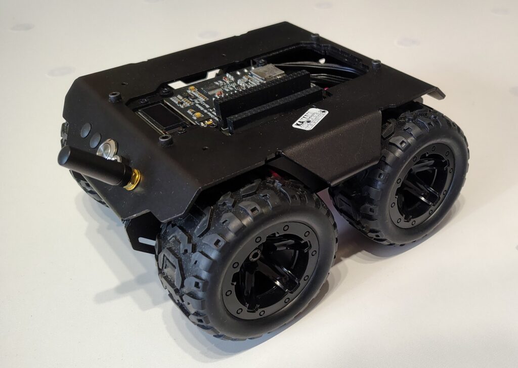
For the hardware component of the project, the Wave Rover platform by Waveshare was utilized as the mechanical base. It is a modular mobile robot designed for expansion with external single-board computers and sensors. Below are the technical details of the structure and the modifications introduced to execute the RFID field exploration project.
Mechanical Structure and Drivetrain
The robot's structure is based on a durable aluminum body that provides rigidity and protection for internal electronic components.
- Drivetrain — A four-wheel drive system is used, with each wheel powered by a direct current (DC) motor equipped with a metal reduction gear. The wheels are electrically coupled in pairs (left and right sides) and connected to independent channels of an H-bridge.
- Drive wheels — The robot is equipped with flexible rubber tires that minimize shocks transmitted to the control electronics and improve traction on uneven terrain.
Modifications and Electronics Integration
The standard Wave Rover platform was adapted to the specific requirements of the project related to the RFID identification system.
1. Drivetrain Control Modernization
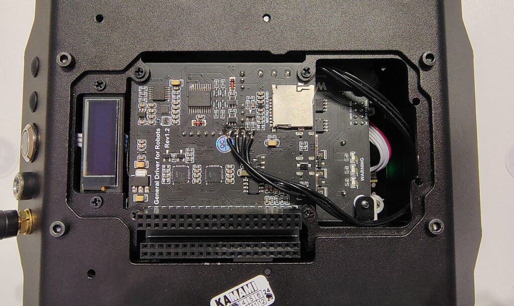
As part of the laboratory implementation, the factory motor control software was abandoned. Instead of standard open-loop control, custom control algorithms were implemented in the ESP32 microcontroller:
- PID controllers — Responsible for stabilizing the rotational speed of the wheels during straight-line motion, compensating for differences in the characteristics of individual motors.
- Bang-bang control — Utilized during the rotation phase due to the unfavorable dynamics of the structure—rotation is executed via differential steering. This allowed for increased precision when rotating the robot along a square grid, which is crucial in the absence of an external positioning system (GNSS).
2. RFID Reader Module
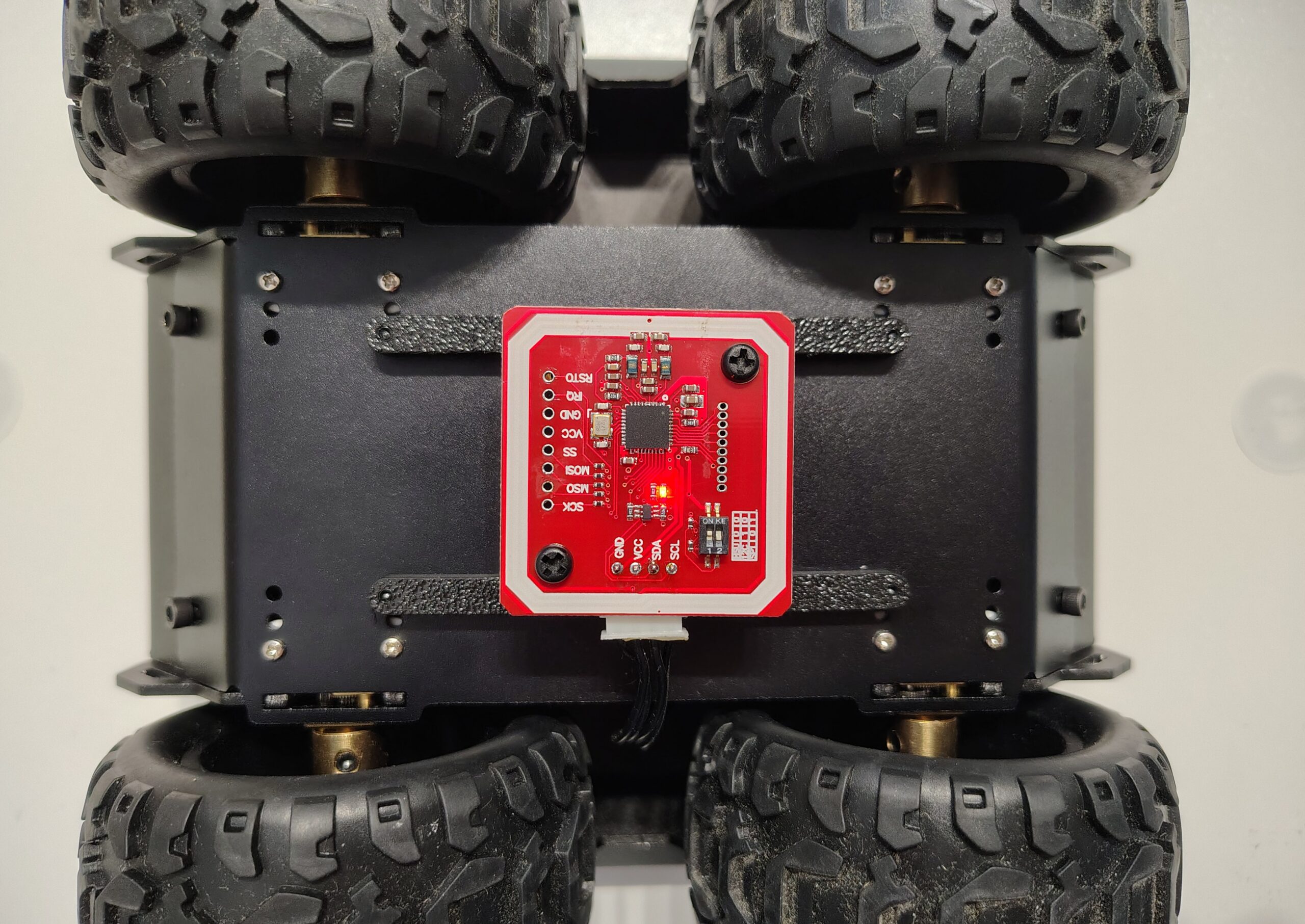
An RFID reader was mounted in the lower section of the chassis, in close proximity to the ground. Its placement was specifically chosen to maximize the read range of the passive RFID tags distributed on the test board, while simultaneously maintaining the ground clearance necessary for movement.