The Problem of RFID Identification in a Workspace
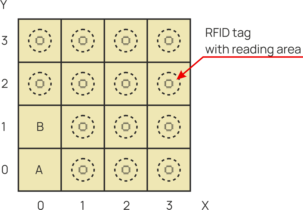
The considered workspace model is discretized into a square grid (shown below on the left). An information carrier in the form of an RFID tag (transponder) is implemented in each grid cell, although the use of Bluetooth technology (beacons) or optical QR codes is also permissible. The location within the grid is defined by Cartesian coordinates (X, Y), corresponding to the column and row numbers. In the preliminary case shown, the system has only identified the tags at positions [0,0] (identifier A) and [0,1] (identifier B). The primary task is so-called exploration (area reconnaissance), which consists of reading the identifiers assigned to the remaining, as-yet-unread grid cells.
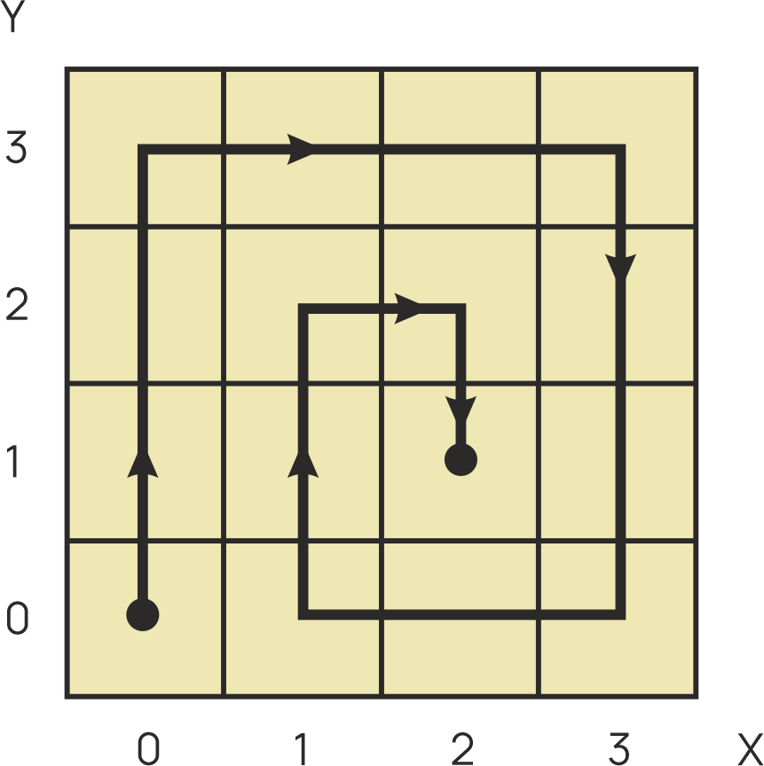
From the possible exploration strategies, a spiral method converging toward the center of the coordinate system was selected. The procedure is initiated in the corner of the workspace, and movement alternates along the X and Y axes. The key control rule is to execute 90° turn maneuvers with a constant turning direction (exclusively in one direction).
The operation scheme is illustrated in the figure below on the right for a right-hand turn variant with the starting point at [0,0]. The robot continues straight-line movement until it reaches the edge of the grid or encounters a cell with an "identified" status. At that point, reorientation (rotation) occurs. The algorithm terminates its operation (stop criterion) when environmental verification indicates that both the cell straight ahead and the one on the turning side have already been recognized.
Solution Architecture with the Robot and Master Unit
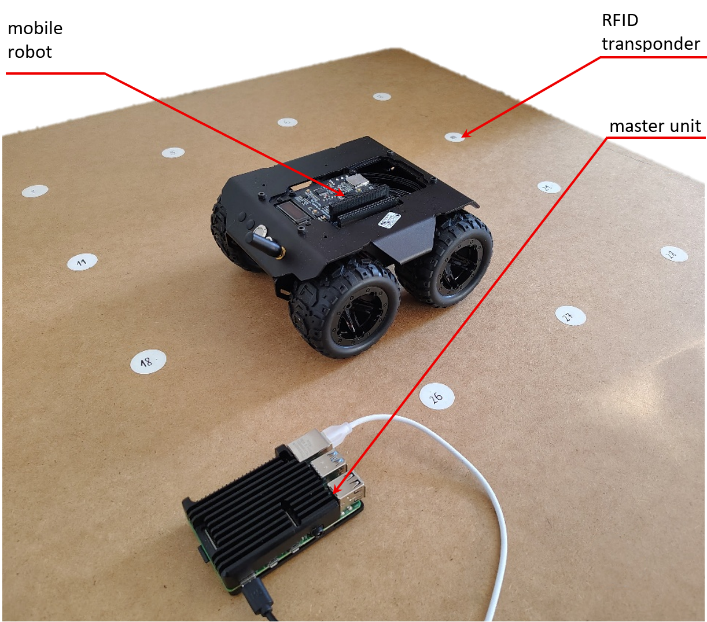
The implemented laboratory system operates without a dedicated positioning system (GNSS RTK). The research environment consists of a board equipped with a matrix of RFID tags, while a mobile robot serves as the execution unit. This platform maintains wireless Wi-Fi communication with the master unit. The system's operation focuses on executing three key processes: coordination of the exploration algorithm, handling data transmission, and controlling the robot's movement.
Cooperation of Three Virtual Machines
Laboratory Implementation
System architecture and resource allocation. The designed system is based on a heterogeneous architecture (different processors), integrating a master unit and an execution unit (slave). The master unit is a Raspberry Pi microcomputer (Broadcom BCM2711 SoC, Cortex-A72), running under the Linux operating system. It is responsible for data processing and generating control commands. The execution unit is the mobile robot, equipped with a Waveshare controller featuring a dual-core ESP32-S3 microcontroller (Xtensa LX7) and managed by the FreeRTOS real-time operating system.
The software implementation is based on three extended virtual machines (VMs) of the CPDev environment. Their numbering reflects the sequence of the exploration process:
- CPDev1 and CPDev2 (Raspberry Pi) — These run on isolated CPU cores, making them independent of the operating system processes. CPDev1 registers the tag map, and CPDev2 executes the navigation algorithm. Communication between them takes place via shared memory (SM).
- CPDev3 (ESP32-S3) — This is responsible for direct drive control and data acquisition from the RFID reader.
Data exchange between the units is carried out wirelessly (Wi-Fi) using the MQTT protocol. This ensures scalability and enables external monitoring. In the event that a tag is missed, the system enters a standby state, awaiting operator intervention. For the logic layer (VM), this situation is interpreted as an extended waiting time for input data.
